A collaboration diagram, also known as a communication diagram, is an illustration of the relationships and interactions among software objects in the Unified Modeling Language (UML). These diagrams can be used to portray the dynamic behavior of a particular use case and define the role of each object.
Collaboration diagrams are created by first identifying the structural elements required to carry out the functionality of an interaction. A model is then built using the relationships between those elements. Several vendors offer software for creating and editing collaboration diagrams.
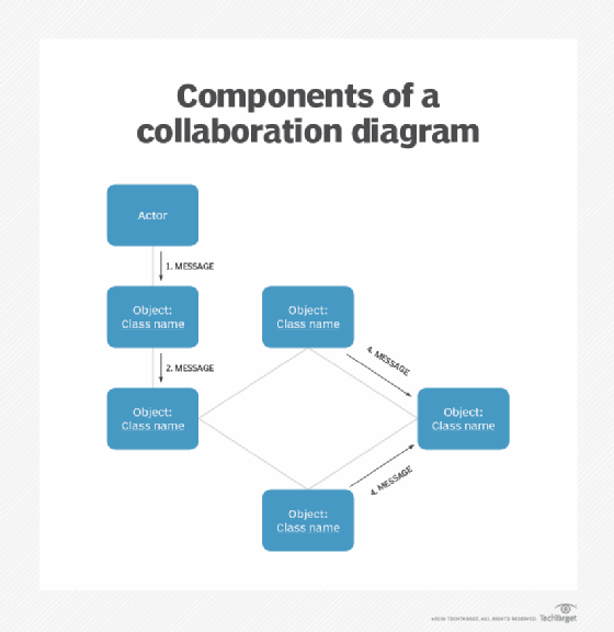
Notations of a collaboration diagram
A collaboration diagram resembles a flowchart that portrays the roles, functionality and behavior of individual objects as well as the overall operation of the system in real time. The four major components of a collaboration diagram are:
- Objects- Objects are shown as rectangles with naming labels inside. The naming label follows the convention of object name: class name. If an object has a property or state that specifically influences the collaboration, this should also be noted.
- Actors- Actors are instances that invoke the interaction in the diagram. Each actor has a name and a role, with one actor initiating the entire use case.
- Links- Links connect objects with actors and are depicted using a solid line between two elements. Each link is an instance where messages can be sent.
- messages- Messages between objects are shown as a labeled arrow placed near a link. These messages are communications between objects that convey information about the activity and can include the sequence number.
The most important objects are placed in the center of the diagram, with all other participating objects branching off. After all objects are placed, links and messages should be added in between.
When to use a collaboration diagram
Collaboration diagrams should be used when the relationships among objects are crucial to display. A few examples of instances where collaboration diagrams might be helpful include:
- Modeling collaborations, mechanisms or the structural organization within a system design.
- Providing an overview of collaborating objects within an object-oriented system.
- Exhibiting many alternative scenarios for the same use case.
- Demonstrating forward and reverse engineering.
- Capturing the passage of information between objects.
- Visualizing the complex logic behind an operation.
However, collaboration diagrams are best suited to the portrayal of simple interactions among relatively small numbers of objects. As the number of objects and messages grows, a collaboration diagram can become difficult to read and use efficiently. Additionally, collaboration diagrams typically exclude descriptive information, such as timing.
Collaboration vs sequence diagrams
In UML, the two types of interaction diagrams are collaboration and sequence diagrams. While both types use similar information, they display them in separate ways. Collaboration diagrams are used to visualize the structural organization of objects and their interactions. Sequence diagrams, on the other hand, focus on the order of messages that flow between objects. However, in most scenarios, a single figure is not sufficient in describing the behavior of a system and both figures are required.
This was last updated in September 2019
Continue Reading About collaboration diagram
- Build your knowledge of UML diagrams
- 4 development tools that bridge the architect-developer gap
- 5 of the best diagram and flowchart software for Windows
- Address goals with various enterprise architecture strategies
Dig Deeper on Software project management
-

'Shift left' doesn't complete DevSecOps story for fintech

By: Beth Pariseau
-
![]()
Ransomware 'businesses': Does acting legitimate pay off?

By: Alexander Culafi
-

Discover 8 network diagramming tools aimed at architects

By: Andrew Froehlich
-

use case diagram (UML use case diagram)
By: TechTarget Contributor

Posted by: carltoncarltonkjeellandea0251977.blogspot.com
Source: https://searchsoftwarequality.techtarget.com/definition/collaboration-diagram#:~:text=A%20collaboration%20diagram%2C%20also%20known,the%20role%20of%20each%20object.
